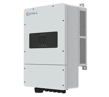
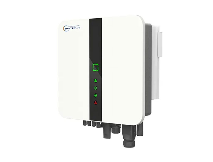
An MPPT solar inverter is an inverter that uses maximum power point tracking to continuously adjust the electrical operating point of connected photovoltaic strings so they can deliver close to their available maximum power.
Solar modules do not produce one fixed combination of voltage and current. Their output changes with irradiance, cell temperature, shading, module condition, and the electrical load applied to them. At any moment, one operating point on the module or string’s current-voltage curve produces the greatest power. Because power equals voltage multiplied by current, the inverter’s control system searches for and follows that point as conditions change.
MPPT is therefore not a separate marketing accessory. It is a central function of modern solar power conversion. It affects startup, energy harvest, string flexibility, response to clouds, operation across seasons, and the ability to handle arrays installed on different roof planes.
Many hybrid, on-grid, off-grid, and microinverter products use MPPT, but they do not all implement it in the same way. They may have one tracker or several independent trackers. Each tracker may accept one string or multiple parallel strings. Voltage, current, full-power range, startup behavior, and algorithm performance vary by model.
Hootrum uses MPPT inputs across relevant solar inverter platforms. Buyers should compare the complete input design rather than assuming that a higher MPPT count always means a better system.
A PV array has a maximum power point because its voltage and current change in opposite ways as the connected electrical load changes, creating one region where their product reaches a maximum.
At open circuit, the module has high voltage but no current, so power is zero. At short circuit, current is high but voltage is close to zero, so power is again near zero. Between those extremes, the current-voltage curve forms a knee. The point near that knee where voltage multiplied by current is greatest is the maximum power point.
The point is not stationary. Stronger sunlight generally increases current. Higher cell temperature generally reduces voltage. Partial shade can create a more complex power-voltage curve with multiple local peaks, especially when bypass diodes become active. Dirt, mismatch, degradation, and different module orientations also change the curve.
An inverter that held the array at one fixed voltage would leave energy unused during many conditions. MPPT algorithms adjust the operating voltage and observe the resulting power. The control loop continues to move as the array changes.
For a simplified example, a string operating at 360V and 10A produces 3.6kW. If the inverter changes operation to 380V and current falls only to 9.8A, power becomes 3.724kW. If it moves to 400V and current falls to 9A, power becomes 3.6kW. In this example, the best of the three points is around 380V. A real tracker evaluates continuously and at much finer resolution.
MPPT tracking works by deliberately changing PV operating conditions, measuring the resulting voltage and current, calculating power, and deciding the next adjustment.
One widely discussed method is perturb and observe. The controller changes voltage slightly and checks whether power rises or falls. If power rises, it continues in the same direction; if power falls, it reverses. Another approach, incremental conductance, uses the slope of the power-voltage relationship to estimate whether the operating point is to the left or right of the maximum. Manufacturers may use enhanced, adaptive, or proprietary combinations.
Tracking quality includes more than steady-state accuracy. A good system must start correctly, find the relevant peak, follow gradual temperature changes, respond to passing clouds, avoid unnecessary oscillation, and recover from abrupt shade. Under complex partial shading, an algorithm may need to scan a wider voltage range to avoid remaining at a local peak that is lower than the global maximum.
The algorithm operates within hardware limits. It cannot track below the minimum MPPT voltage, above the maximum, or beyond current limits. It also cannot correct a fundamentally poor string design, such as excessive cold-weather open-circuit voltage or different arrays forced onto one input.
The hybrid inverter selection process should therefore combine algorithm questions with electrical design. Ask for MPPT range, starting voltage, full-power range, maximum input current, short-circuit current, independent tracker count, strings per tracker, and any model-specific PV oversizing rule.
MPPT voltage range, starting voltage, and maximum PV voltage are different limits that control whether a string can start, track effectively, and remain electrically safe.
Maximum PV voltage is an absolute upper limit. The array’s cold-weather open-circuit voltage must remain below it. Because module voltage rises as temperature falls, using standard-test-condition Voc without a temperature correction can create an unsafe design.
Starting voltage is the approximate input level required for the inverter to wake up and begin conversion. A string may have enough open-circuit voltage to start in the morning but still lack enough power for meaningful output.
MPPT operating range is the voltage window in which the tracker can regulate the array. The string’s working voltage should remain inside this window across expected temperature and irradiance conditions.
Full-power MPPT range is narrower on some products. The inverter may track at a low voltage but be unable to deliver rated power because current limits are reached. This detail matters when designing high-power arrays with short strings.
For example, Hootrum’s current HB3125EH048 three-phase hybrid model page lists a maximum PV input voltage of 1000Vdc, a starting voltage of 120Vdc, an MPPT input range of 120–850Vdc, and a full-load MPPT voltage range of 295–850Vdc. These numbers demonstrate why “the voltage is inside the MPPT range” is not the only check. Exact values must always be taken from the ordered model’s datasheet.
MPPT current limits determine how many strings and what module technologies can be connected without exceeding the inverter input stage.
Modern high-power modules can deliver more current than older module generations. Bifacial modules can also produce additional rear-side current under favorable conditions. An inverter designed around lower-current modules may have acceptable voltage but insufficient current capacity for the proposed string arrangement.
Two values are especially important. Maximum operating current limits how much current the inverter can use during normal production. Maximum short-circuit current is a safety-related input limit based on the array Isc. Both must be checked per tracker or input according to the datasheet.
When two strings are paralleled on one MPPT, their currents add. Voltage does not add in parallel. If each string has an Imp of 13A, two parallel strings produce about 26A at the operating point before considering irradiance or bifacial adjustments. If the MPPT operating-current limit is lower, the inverter may clip current or the design may be noncompliant.
Current limits also influence asymmetric input designs. A datasheet may state different current capacity on different MPPT channels, such as a 2+1 string arrangement. The designer should assign strings accordingly rather than treating every connector as identical.
Multiple MPPT means that an inverter contains two or more independently controlled PV input groups, each able to operate at its own voltage and maximum power point.
This independence is useful when arrays experience different conditions. An east-facing string may reach its best point at a different voltage from a west-facing string. A shaded lower roof may behave differently from an unshaded upper roof. Separate MPPTs prevent one group from forcing the other to operate at the same voltage.
Multiple connectors do not always mean multiple trackers. One MPPT may have two string inputs that are internally paralleled. Those strings normally need similar module type, string length, orientation, and irradiance. Buyers should read “number of MPPTs” and “strings per MPPT” as separate specifications.
For example, a notation such as “2 / 2+1” can indicate two independent trackers, with two string inputs assigned to one tracker and one string input assigned to the other. The exact interpretation should be confirmed in the manual and wiring diagram.
More trackers can simplify complex roofs and reduce mismatch, but they add no benefit when all strings are identical and operate under uniform conditions. The best design uses enough independent trackers for the actual array groups without paying for unnecessary complexity.
The number of MPPTs a solar project needs is approximately the number of electrically distinct PV groups that should operate at different voltages.
Begin by grouping modules with the same model, series count, orientation, tilt, and shading profile. A simple south-facing roof with two identical strings may need one MPPT with two string inputs if current limits allow. An east-west roof typically benefits from at least two trackers. A three-plane roof may need three, unless two planes have sufficiently similar conditions and can be combined within design limits.
Partial shading requires judgment. A small chimney shadow that moves across a few modules may not justify a separate tracker if string layout and bypass behavior are acceptable. Persistent shade affecting one roof section may justify separation or module-level power electronics.
Module mismatch also matters. Strings connected in parallel on the same tracker should normally have equal series module counts. Different string lengths produce different operating voltages and should not be paralleled casually.
Commercial roofs may have repeated sections with identical orientation, allowing several strings per tracker. Large high-voltage hybrid systems may offer several MPPT channels to divide the roof into manageable zones. The designer must check current per tracker and input connector count.
A high MPPT count should not become a sales goal by itself. Correct grouping, current capacity, algorithm behavior, monitoring resolution, and serviceability are equally important.
MPPT performance under partial shading depends on array topology, bypass-diode behavior, tracker independence, and the algorithm’s ability to identify the most productive operating peak.
When modules in a series string receive different irradiance, the shaded modules restrict string current until bypass diodes conduct around affected cell groups. The resulting power-voltage curve can contain several peaks. A conventional tracking routine may settle on a local peak, while a global scan can search for a higher one.
Separate MPPTs help when shading is concentrated in one array group. They do not eliminate loss inside a shaded string. Module-level electronics, such as microinverters or optimizers, can allow more granular operation, but they add components, connectors, communications, and service considerations.
Microinverters are particularly relevant for irregular roofs because conversion and tracking occur at individual modules or small groups. Buyers researching solar micro inverter manufacturers should compare module compatibility, maximum input current, AC trunk design, monitoring, rapid-shutdown requirements, enclosure durability, and battery integration rather than evaluating only peak efficiency.
Shade analysis should be based on the real site. A satellite image or annual simulation can identify trees, chimneys, parapets, neighboring buildings, and seasonal sun paths. The resulting array grouping should then be matched to the available MPPT inputs.
An MPPT inverter and an MPPT charge controller both track PV maximum power, but they occupy different positions in the system and perform different conversion functions.
| Feature | MPPT Inverter | MPPT Charge Controller |
|---|---|---|
| Main output | Produces AC power and may also manage a battery | Produces controlled DC charging power for a battery |
| System role | PV conversion, grid interaction, backup, monitoring, and possibly bidirectional storage control | PV-to-battery charging in a DC-coupled system |
| Grid synchronization | Present in on-grid and hybrid products | Normally not a grid-synchronizing device |
| Battery requirement | Depends on inverter type | Generally charges a battery bank |
| Typical application | Grid-tied PV, hybrid storage, AC loads, export control | Off-grid battery charging, DC systems, separate inverter architecture |
Some off-grid inverter-chargers integrate both functions in one enclosure. Others use a separate MPPT charge controller and battery inverter. The integrated approach can simplify communication and installation, while separate components can provide design flexibility and redundancy.
Do not connect a separate controller and hybrid inverter to the same array or battery without an approved architecture. Charge limits, voltage sensing, communication, and protection must be coordinated.
MPPT and PWM are different solar charging approaches, with MPPT using power conversion to operate the array near its best voltage while PWM effectively pulls array voltage toward battery voltage during charging.
A PWM controller can be simple and economical for small systems where the module and battery voltage are closely matched. However, it cannot generally convert excess panel voltage into additional charging current in the way an MPPT converter can.
Consider a simplified module operating near 36V and 10A at maximum power, or 360W. If a PWM controller connects it to a battery charging around 14V, the array operating voltage moves much lower, and much of the potential voltage is not converted into useful current. An MPPT converter can operate near the higher module voltage and step the power down to battery voltage at higher current, subject to efficiency and limits.
This example is intentionally simplified. Actual performance varies with temperature, battery state, irradiance, wiring, controller quality, and module selection. The key point is that MPPT provides voltage-conversion flexibility and is better suited to higher-voltage arrays and changing conditions.
In modern hybrid inverter systems, MPPT is normally expected. The meaningful comparison is often not MPPT versus PWM, but one MPPT versus multiple MPPTs, input current capability, tracking range, and global-peak behavior.
MPPT interacts with battery charging and load supply by determining available PV power, while the hybrid inverter decides how that power is distributed within system limits.
If PV production is 8kW, active loads use 3kW, and the battery can accept 4kW, one kilowatt remains. The inverter may export it, curtail it, or feed a controllable load. If export is prohibited and the battery is full, the MPPT system deliberately moves the array away from its maximum point to reduce production. This is normal curtailment, not tracking failure.
If the battery is cold or near full state of charge, the BMS may reduce allowable charge current. The inverter then has less capacity to absorb surplus PV. If loads increase, it can move back toward the maximum point.
During backup operation, PV may need to match load and battery conditions within an isolated microgrid. Rapid load changes, battery limits, and available sunlight influence control stability. The system designer should verify how the inverter handles battery full conditions, minimum load, generator interaction, and black start.
Commercial projects may intentionally curtail PV to maintain zero export or a site import target. A meter or CT at the point of connection sends feedback to the inverter. Correct CT orientation and communication are essential; a reversed signal can cause incorrect export behavior.
MPPT design for single-phase and three-phase hybrid inverters follows the same PV principles but differs in power level, string voltage, current distribution, and system application.
Residential single-phase models often use lower or medium PV string voltages and two to four trackers depending on power class. This supports common multi-plane roofs. The battery side may use 24V, nominal 48V, or another low-voltage range.
Three-phase commercial products often accept longer strings and higher PV voltage to reduce current and cable loss across larger arrays. They may include more MPPT channels and multiple string inputs. High-voltage batteries can support larger power with lower DC current, while low-voltage three-phase models use high current and require robust battery cabling.
Hootrum’s three phase hybrid inverter category includes high-voltage models intended for scalable commercial applications. Current product pages show model-specific differences in MPPT count, battery range, PV voltage, protection, and power. Buyers should avoid copying one model’s input design to the entire series.
For either phase type, MPPT grouping should be reflected in monitoring. Being able to view voltage, current, power, and alarms by tracker helps commissioning teams identify reversed strings, blown fuses, shading, mismatch, and connector problems.
A worked MPPT string-design example demonstrates how module voltage and current are compared with inverter limits before installation.
Assume a module has Voc of 50V, Vmp of 41V, Isc of 14A, and Imp of 13.2A at standard test conditions. Suppose the preliminary design uses 14 modules in series. The string Vmp is approximately 14 × 41V = 574V, and standard-condition Voc is 14 × 50V = 700V.
Cold-weather Voc must then be calculated using the module’s voltage temperature coefficient and the site’s minimum design temperature. If the corrected string Voc rises to 780V, it remains below a hypothetical 1000V maximum. The 574V working value must also remain inside the MPPT range under hot conditions, when Vmp falls.
If one string is connected to an MPPT, operating current is approximately 13.2A. If two identical strings are paralleled, operating current becomes about 26.4A and short-circuit current becomes about 28A before any required design factor. Both values must remain within the inverter’s per-MPPT limits.
If the roof has east and west groups, place them on separate trackers. If one group uses 14 modules per string and the other uses 12, they should not be paralleled on the same tracker because their best operating voltages differ.
This is a conceptual example. Final design must follow local codes, module and inverter instructions, temperature calculations, conductor ampacity, protection requirements, and qualified engineering review.
MPPT numbers in a B2B quotation should be precise, model-specific, and sufficient for the buyer to validate the proposed PV design.
Maximum PV input power and any permitted DC/AC oversizing condition.
Absolute maximum PV input voltage.
PV startup voltage.
MPPT operating voltage range.
Full-power MPPT voltage range, when specified.
Nominal or rated PV input voltage.
Number of independent MPPT trackers.
Number of string inputs per tracker.
Maximum operating current per MPPT.
Maximum short-circuit current per MPPT.
Maximum backfeed current, where relevant.
Permitted module types and grounding arrangement.
The quotation should also identify the exact model, firmware family, grid standard, battery interface, and environmental limits. If product customization changes connectors, input current, or software, the revised specification should be controlled and approved.
MPPT performance testing uses a programmable PV simulator or controlled array to verify startup, tracking accuracy, dynamic response, input limits, and behavior under nonuniform conditions.
Start with basic verification at several voltages and power levels. Confirm that each tracker starts within the stated conditions, reaches stable operation, and reports realistic voltage, current, and power. Compare DC input power with AC output and charging power while accounting for conversion losses.
Test trackers independently. Apply different simulated irradiance profiles to separate MPPT inputs and confirm that one does not improperly force the other. If the product has two string connectors on one tracker, verify current sharing and monitoring behavior.
Simulate moving clouds by changing the available maximum point. Observe response speed, oscillation, and stability. For products claiming global MPPT, apply a multi-peak curve and check whether the controller finds the higher peak within an acceptable period.
Test limit behavior. Approach the high and low ends of the MPPT voltage range, current limit, and startup threshold. Confirm that alarms are accurate and that the product recovers safely. Also test zero-export curtailment, battery-full curtailment, and load changes because these can intentionally move the array away from maximum power.
Document ambient temperature, firmware, simulator calibration, wiring, settings, and pass criteria. Sample approval should be linked to production change control.
Common MPPT design mistakes result from treating panel wattage as the only input requirement and ignoring voltage, current, grouping, temperature, and control behavior.
Cold-weather overvoltage: Standard-condition string Voc is below the limit, but corrected winter voltage is not.
Hot-weather undervoltage: String Vmp falls below the useful tracking or full-power range.
Excess current: Modern modules or parallel strings exceed the tracker’s operating or short-circuit limit.
Mixed orientations on one tracker: East, west, shaded, and unshaded groups are forced to one voltage.
Unequal string lengths in parallel: Strings cannot operate at their individual optimum voltages.
Counting connectors instead of trackers: Three PV connectors are assumed to mean three independent MPPTs.
Ignoring curtailment: Reduced PV output caused by full batteries or zero-export control is mistaken for MPPT failure.
No monitoring by tracker: Commissioning teams cannot isolate mismatch or wiring faults.
Using category specifications for every model: A range stated on a collection page is copied to products with different hardware.
No sample validation: Bulk orders are placed without dynamic tracking, thermal, and communication testing.
An MPPT solar inverter buyer checklist connects the PV array, inverter input stage, battery system, grid connection, and service requirements into one approved design.
Provide the module datasheet, including Voc, Vmp, Isc, Imp, and temperature coefficients.
State the minimum and maximum site temperatures used for design.
Provide modules per string and strings per MPPT.
Separate arrays by orientation, tilt, module type, and shading profile.
Verify cold Voc, hot Vmp, operating current, and short-circuit current.
Confirm MPPT count, strings per tracker, and asymmetric current capacity.
Check startup and full-power voltage ranges, not only the broad MPPT range.
Define PV oversizing, export limits, battery charge limits, and curtailment behavior.
Request tracker-level monitoring and alarm information.
Test startup, dynamic tracking, multi-peak behavior, and recovery on a sample.
Confirm model-specific certificates, manuals, firmware, and warranty.
Have the final string design reviewed by a qualified engineer or installer.
These frequently asked questions clarify the difference between MPPT count, input count, voltage range, and actual system performance.
Most modern grid-connected, hybrid, and many off-grid solar inverters use MPPT, but the number of trackers and their capabilities vary. Very simple or legacy charging systems may use PWM or another approach. Always check the datasheet rather than relying on the product category name.
No. More independent trackers are useful for arrays with different orientations, shading, or string conditions. A simple uniform roof may not benefit from additional trackers. Current limits, voltage range, algorithm quality, monitoring, cost, and reliability also matter.
They can be electrically connected in some designs, but forcing different orientations to one operating voltage can reduce harvest. East and west arrays are normally placed on separate trackers when possible. A site-specific simulation can quantify the effect.
The inverter may fail to start, stop tracking, operate at reduced power, or cycle on and off depending on the voltage and available power. String length should be designed so working voltage remains within the useful range across expected temperatures.
Possible causes include load and battery limits, zero-export control, a full battery, current clipping, thermal derating, grid restrictions, shading, string mismatch, faults, or incorrect settings. Intentional curtailment should be distinguished from MPPT tracking problems.
Send the module datasheet, modules per string, number of strings, roof orientations, shading information, site temperature range, target inverter model, battery system, and export requirement. Hootrum can then check the proposed arrangement against the model-level voltage and current limits.
MPPT is the control function that allows a solar inverter to extract useful power from a PV array as sunlight and temperature change. Its real value depends on the complete input design: tracker count, string grouping, voltage window, current limits, algorithm behavior, monitoring, and interaction with batteries, loads, and export control.
For simple roofs, one or two trackers may be sufficient. For mixed orientations, persistent shading, or larger commercial arrays, multiple independent MPPTs can improve design flexibility and reduce mismatch. However, no tracker can correct unsafe string voltage, excessive current, incompatible parallel strings, or weak commissioning.
Before purchasing an MPPT solar inverter in volume, send Hootrum a complete module and string plan, verify the exact datasheet, and test representative samples under dynamic conditions. This approach turns “MPPT” from a marketing label into a measurable system requirement.
1. U.S. Department of Energy — Solar Integration: Inverters and Grid Services Basics: https://www.energy.gov/cmei/systems/solar-integration-inverters-and-grid-services-basics
2. Wikipedia — Pulse-width modulation: https://en.wikipedia.org/wiki/Pulse-width_modulation
3. Wikipedia — Maximum Power Point Tracking: https://en.wikipedia.org/wiki/Maximum_power_point_tracking
 English